
WoodJoint and NextFEM. The new timber joints plugin
8 February 2022FireRating-C 1.0 structural fire analysis
In order to proceed with the structural fire analysis of a garage built in the 70s it is necessary to carry out the structural fire design with an analytical method of some structural elements subject to fire which will be carried out with the aid of FireRating-C .
In this specific case for the fire design, it was decided to reinforce part of the floors below the houses with polyurethane paints to better partition the garages from the residential portion, while for the area of the floors below the driveways and gardens, the method of analytical verification was chosen. If the elements are suitable after the fire test in the event of a 90 minutes fire, it is possible not to adopt expensive paints even on the floor concrete and therefore allow a much cheaper intervention and in any case in compliance with the required requirements.
Verification of effective concrete covers
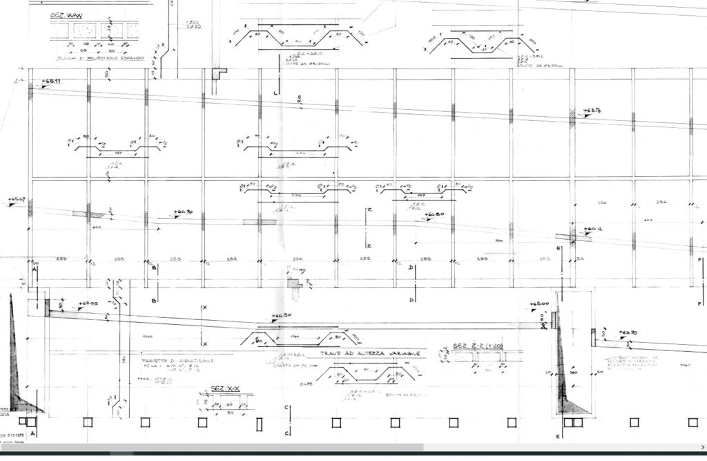
Since the concrete cover plays a fundamental role in the verification of the elements subject to fire, on the basis of the carpentry and the drawings of the bars reported in the original documents, the geometry of the sections and bars was reconstructed with the relative folds of the reinforcements.

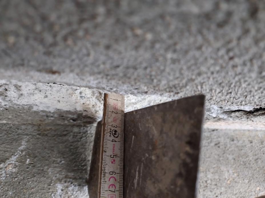
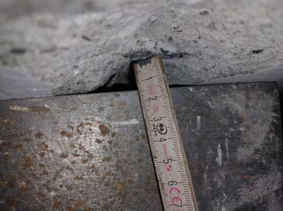
Based on the geometry of the carpentry, a real concrete cover of 13.6 mm is expected. For further verification, two different on-site surveys were carried out to check this information.
Static schematics and project loads
The verification of the stresses must be carried out on the basis of permanent loads indicated in the original desgin while regarding to the variable loads it’s needed to consider the current loads reported in the thecnical codes. In accordance with the Eurocodes, the factoring of the actions must be done in Ultimate Limit States in Exceptional conditions (fire).

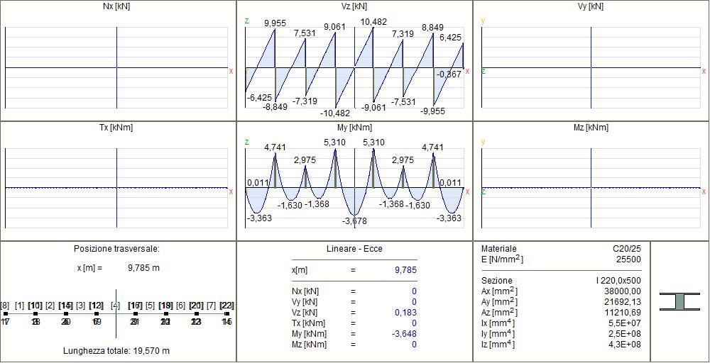
Therefore, on the basis of the loads and the geometry of the spans obtainable from the carpentry drawings, the static scheme of a continuous beam was reconstructed which schematizes the floors subjected to verification.
Fire analysis with FireRating-C
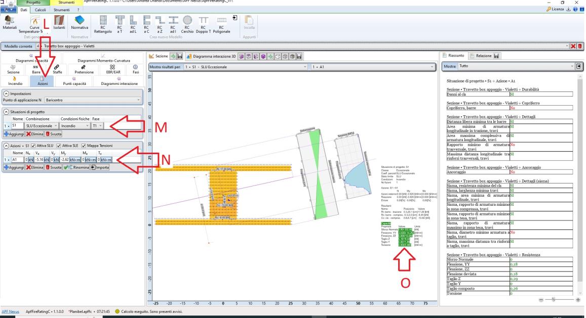
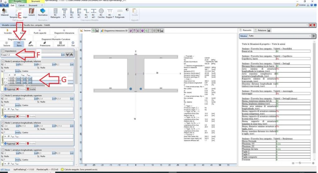
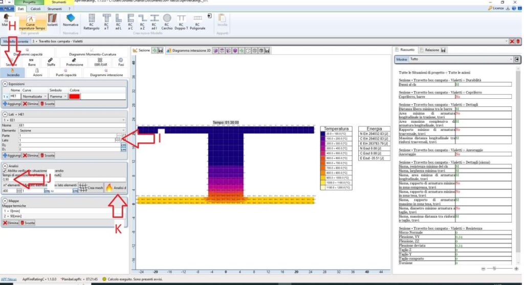
Following the retrieval of all the information obtained in the previous paragraphs, the checks of the floor were carried out for fire design. The procedure should be carried out both for the more onerous situation in support and also in the span as the combination of calculation stress is different. This following images shows the steps relating to the support check.
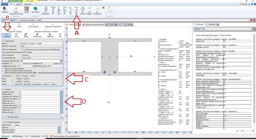

- A – The new section is created as a beam type with lightened block
- B – You enter the “Section” table
- C – The materials of the section taken from the original documents are set
- D – The geometric information of the section is entered
- E – You enter the “Reinforcing bars” table
- F – On site verified concrete cover is selected
- G – Enter the data of the bars present in the verification section
- H – You enter the table “Fire”
- I – The parts of the section subject to direct fire are entered
- J – The exposure time required for resistance verification is set
- K – After creating the finite element mesh, the thermal analysis is launched
- L – You enter the “Actions” table
- M – The required combination is set
- N – The data of the support stresses of the joist are entered
- O – The checks of the section subject to fire are carried out automatically
The same procedure can be repeated as regards the verification of the supported beam. The calculation report can be exported to have a detailed report of all the regulatory checks carried out, both geometric, construction details and strength.


